Friday, 7 July 2017

Water Level Controller

Water Level Controller

This article explains you how to detect and control the water level in an overhead tank or any other container. This water level controller system monitors the water level of the tank and automatically switches ON the motor when ever tank is empty. The motor is switched OFF when the overhead tank or container is FULL. Here the water level of the tank is indicated on LCD (Liquid crystal Display). Using this system, we can avoid the overflow of the water. We have already seen How water level indicator circuit works using AVR Microcontroller in the earlier post. But, here we are designing the circuit which is used to detect and control the water level automatically in overhead tank using 8051 microcontroller.
In this system water sensing can be done by using a set of 4 wires which are placed at different levels in tank. DC supply probe is placed at the base of the tank.

Water Level Controller using 8051 Circuit Principle:

This system mainly works on a principle that “water conducts electricity”. The four wires which are dipped into the tank will indicate the different water levels. Based on the outputs of these wires, microcontroller displays water level on LCD as well as controls the motor.
Taking quality as our motto, we are engaged in manufacturing and supplying Automatic Water Level Controller. Our given range of water level controllers is acclaimed in the industry for their attributes. This water level controller is made up of finest material & leading edge technology. The offered water level controller is properly examined on different parameters of quality in order to make certain their quality. Our customers can take these water level controllers from us at nominal rates.

Rain Alarm Project

Rain Alarm Project

The main purpose in designing this Rain Alarm project is to provide proper irrigation system in the field of agriculture. It is mainly used to reduce human intervention.  Rain Alarm comprises of soil moisture sensor, a transistor driver and a fan motor indicating a pump.
When soil moisture condition is fully wet, sensor changes the output logic to de-energized driver to make pump motor OFF. When soil moisture condition is dry sensor changes the output logic to  turn the pump motor ON.
Kit Contents: Sensor, Solderless Multipurpose breadboard, Set of Components, Accessories, Connector, Motor, Wire.
With this solderless breadboard approach none of the component is soldered, hence all the components can be used again and again to try such multiple circuits.

Working:

Water is a conductor of electricity. When water is in contact with the probe then there is a flow of current toward the base of  NPN transistor (BC548), which conducts. With the conduction of NPN transistor, electron reaches to Q2, which is a PNP transistor . PNP transistor (BC558) also conducts and current flows through the speaker. In a speaker there is inductive coil which causes motion in one direction and after that produces induce current, which is in opposite direction to the flow of current this induced current in the form of pulse, flows through a capacitor, resistance and makes 1st transistor BC548 off for an inter-well and after-that it relaxes to previous state. This process repeats again and again till probe is in contact with water and an oscillation is created in the circuit. Speaker diaphragm vibrates and gives a tone.
Block Diagram

Remote monitoring of patient body temperature over internet

Remote monitoring of patient body temperature over internet

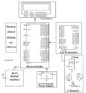
The main aim of the Remote Monitoring of Patient Body Temperature is to acquire real-time body temperature of a person remotely over internet falling under the category of Internet of Things-IOT. For this real-time scenario we take one digital temperature sensor, interfaced to a micro-controller of 8051 series to send live data to a remote location anywhere in the world over internet.

The data is directly sent through a Wi-Fi module interfaced to the micro-controller under TCP IP protocol to a dedicated IP on the cloud via networked wireless modem environment.
Itdisplays the data in real time chart form such as line type, bar type, pie  type etc. in any internet connected PC / Laptop either for viewing by self or by public.. The real time data is also seen at the sending end upon a LCD display interfaced to the microcontroller.
 The power supply consists of a step down transformer 230/12V, which steps down the voltage to 12V AC. This is converted to DC using a Bridge rectifier and it is then regulated to +5V using a voltage regulator 7805 which is required for the operation of the microcontroller , 3.3 volt for the Wi-Fi unit and other components. 

Block Diagram:


Remote monitoring of transformer

Remote Monitoring of Transformer:

The main aim of the Remote Monitoring of transformer is to acquire real-time data of distribution transformers remotely over internet falling under the category of Internet of Things-IOT. As we know, in our power system the transformer and generator are our expensive and important equipment’s.  If anyone from both is damage or trip due to any reason such as temperaturecurrent or voltage then the whole supply would be switched offed. Then the time and money both would be waste, so the real-time monitoring of transformer and generator is mandatory for supplying the smooth supply to the consumer. Different companies and peoples are working for the real-time monitoring and protection of these expensive equipment’s but their system cost and size is so much high anywhere in the world.

Here we have designed a system that is called the remote monitoring of transformer /generator health over internet with the help of pic micro-controller 18F 452, temperature sensor, current sensor, voltage sensor, Wi-Fi module and analogue to digital converter. By using this system, the user or supply company can easily check the instant status of their transformer or generator at their homes through the internet WI-FI service. Pic micro-controller is used in this embedded system project project. you may also like to check pic micro-controller tutorials for beginners and experts.
 The power supply consists of a step down transformer 230/12V, which steps down the voltage to 12V AC. This is converted to DC using a Bridge rectifier and it is then regulated to +5V using a voltage regulator 7805. It is required for the operation of the micro-controller , 3.3 volt for the Wi-Fi unit and other components. 

IOT based Home Automation Over the Cloud

IOT based Home Automation Over the cloud

Short Description :-

Abstract:
The main purpose of this IOT Based Home automation project is to control any load through the Internet network over cloud. It works  remotely on the basic principle of the Internet of things (IOT). For this real-time scenario we use webpage with user configurab
le front end to control and monitor the load. The data sent from from a password protected webpage returns commands through allotted IP fed to it. A Wi-Fi Module is configured with any nearby wireless modem to access internet.  The  received internet commands are fed to the Wi-Fi module. The program within the Wi-Fi Module execute the received commands based on which the load  gets activated through TRIAC and Opto-coupler interfaced to Wi-Fi Module. The status of the load also will be displayed on the web page.
Here in this project program in written within the Wi-Fi module, No extra microcontroller has been used to drive the load.
The power supply consists of 5V SMPS board and 3.
3V voltage regulator for a Wi-Fi module. 5V SMPS board will give 5V DC out from 230V AC, this we fed to 3.3V voltage regulator which supply power to Wi-Fi module and remaining circuit.
Block Diagram: